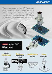
-
BCAK Series -
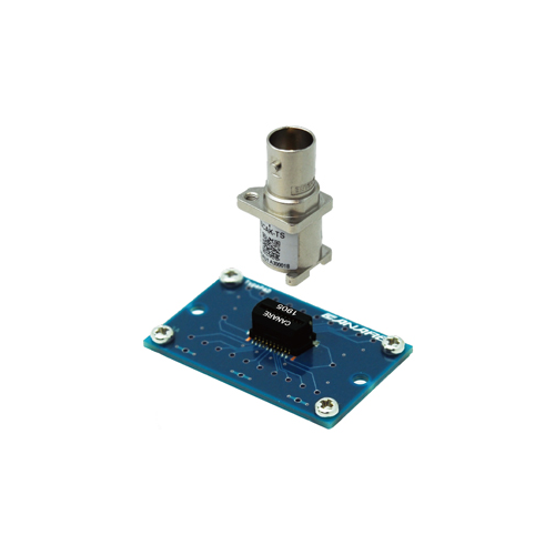
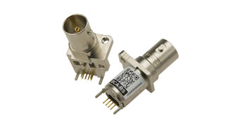
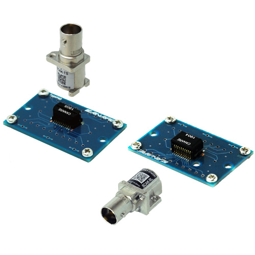
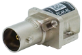
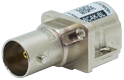
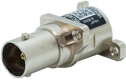
BCAK-TS + AKU-20SFYG -
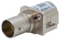
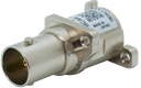
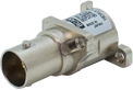
BCAK-RL + AKU-20LFYG -
About 12G-SDI Active BNC
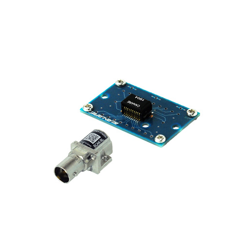
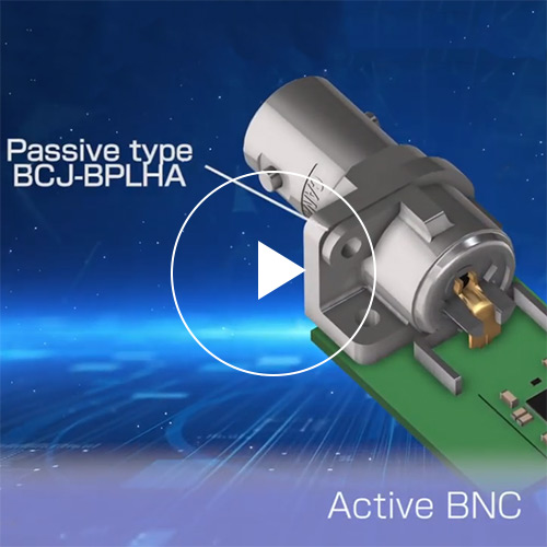
12G-SDI Active BNC
12G-SDI Active BNC integrating I/O interface device inside. It frees you from struggling with PCB design coping with return loss and board space.
Key Features and Benefits
- Assembled on a PC board with SMT Card Edge Connector.
The pluggable 2-piece structure improves productivity and replaceability.
*Card Edge Connector sold separately - Supports 12G/6G/3G/HD/SD-SDI
- Reduce entire development cost as wel as development period.
- 16 mm: Minimum pitch between adjacent connectors
- Straight models can be mounted on the same board at the same height as 3G-SDI Active BNC.
- PIN control: status monitoring and mode change
- Command control for optimization and characterization
- Cable driver and equalizer with reclocker
- TX/RX/BiDi identification by insulation color
- Note:
- Card Edge Connector NOT included
- Tech Data
- Leaflet
- Movie
BCAK12G-SDI
| Type | Model | Form | Type | Built-in | Sales unit |
|---|---|---|---|---|---|
 |
BCAK-TL | Right Angle |  |
Cable Driver | 5 pcs |
 |
BCAK-RL |  |
Cable Equalizer | ||
 |
BCAK-BL |  |
Cable Driver & Equalizer | ||
 |
BCAK-TS | Straight | |
Cable Driver | |
 |
BCAK-RS | |
Cable Equalizer | ||
 |
BCAK-BS | |
Cable Driver & Equalizer |
SMT Card Edge Connectors12G-SDI
| Type | Model | Form | Suit for | Sales unit |
|---|---|---|---|---|
 |
AKU-20LFYG | Right Angle | BCAK-TL BCAK-RL BCAK-BL |
5 pcs or (500 pcs / reel) |
 |
AKU-20SFYG | Straight | BCAK-TS BCAK-RS BCAK-BS |
Key Features and Benefits / SMT Card Edge Connectors
- Card Edge Connector for BCAK
- Same footprint for TX, RX and BiDi
- Applicable for reflow soldering
Specifications
| Type | TX | RX | BiDi TX mode | BiDi RX mode |
|---|---|---|---|---|
| Supply Voltage | DC 2.5 V | |||
| Current Consumption | 195 mA | 125 mA | 128 mA | 115 mA |
| Operating Temperature | -40 °C to +85 °C | |||
| Output Amplitude | 800 mV | N/A | 800 mV | N/A |
| Equalization | N/A | 12G-SDI 100m over L-5.5CUHD |
N/A | 12G-SDI 100m over L-5.5CUHD |
| Standards | SMPTE ST 2082-1, 2081-1, 424, 292, 259 BTA S-004C, EN 50083-9 |
|||
| Weight | Right Angle: 9 g, Straight: 10 g | |||
< Panel Hole Dim. >
| Right Angle | Straight | |
|---|---|---|
| Panel Hole Dim. |  t1.6 Screw: M2.6 |
 t1.6 Screw: M2.6 |
| PCB Hole Dim. | 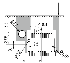 use a M2.6 screw to fix BCAK to PCB. |
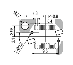 use a M2.6 screw to fix BCAK to PCB. |
- The dark shaded areas come into contact with the connector body.
Technical Note
Voltage Standing - wave Ratio (VSWR) and Return Loss
Terminating the receiving end of a limited length coaxial cable using a resistance value not equal to its characteristic impedance creates a reflected wave that returns back down the cable to the sending end. The result is interference developing between the travelling wave and the return wave which results in a standing wave that causes voltage levels to fluctuate. The degree to which terminating resistance matches the characteristic impedance is indicated using the VSWR or voltage standing-wave ratio standard shown in Fig. 1. Going hand in hand with the VSWR ratio is the return loss factor which measures the size of the reflected wave current in relation to the travelling wave current. (See Fig. 2)
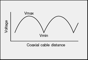
Fig. 1 Voltage Distribution Over Coaxial Cable
| VSWR | Return Loss (dB) |
|---|---|
| 2 | 9.54 |
| 1.5 | 13.98 |
| 1.2 | 20.83 |
| 1.1 | 26.44 |
| 1.05 | 32.26 |
| 1.02 | 40.09 |
| 1.01 | 46.06 |
Fig. 2 VSWR to Return Loss Conversion Table