-
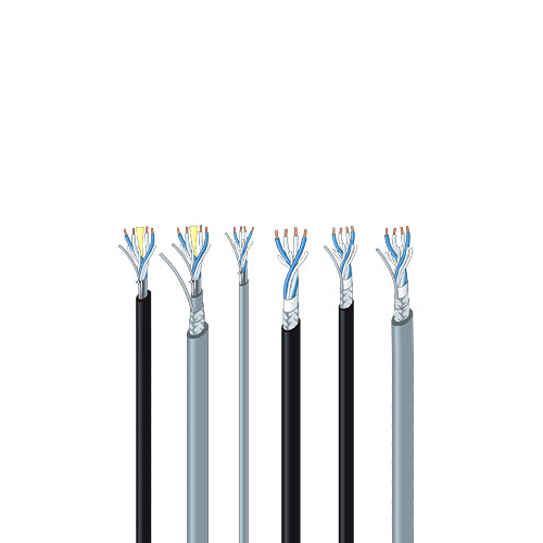
Star Quad Microphone Cables (Single)
Star Quad Microphone Cables (Single)
Effectively reduce noise levels to 1/10 that of general-purpose, 2-conductor shielded cables.
- TECH DATA
- TECH NOTE
- DOWNLOAD
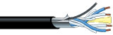
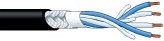
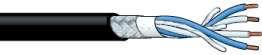
Aluminum Foil Shield
| Type | Model | Sales units | Nom. O.D. | Weight | Composition | Electrical characteristics | ||||||
|---|---|---|---|---|---|---|---|---|---|---|---|---|
| No. of cond. | Cross sec. area (AWG) and cond. comp. |
Twist pitch | Shield | Cond. DCR | Shield DCR | Nom. cap.* | Nom. cap.** | |||||
| m | mm | kg/100m | mm2/(AWG) Q’ty/mm |
mm | ohm/100m | ohm/100m | pF/m | pF/m | ||||
 Jacket color GRY |
L-4E3AT | 200 500 |
3.0 | 1.2 | 4 | 0.08(28) 7/0.12A |
16 | AL foil | 24.6 | - | - | - |
 Jacket colors BLKGRY |
L-4E5AT | 100 200 400 |
5.0 | 3.3 | 4 | 0.18(25) 16/0.12A |
21 | AL foil | 10.7 | - | 164 | 222 |
| L-4E5ATG | 100 200 400 |
5.0 | 3.3 | 4 | 0.18 (25) OFC 1/0.18 + 30/0.08 |
21 | 11.1 | - | 164 | 222 | ||
| L-4E6AT | 100 200 400 |
6.2 | 5.0 | 4 | 0.31(23) 12/0.18A |
25 | 6.4 | - | 150 | 210 | ||
| L-4E6ATG | 100 200 400 |
5.8 | 4.6 | 4 | 0.34 (22) OFC 1/0.18 + 63/0.08 |
35 | 5.5 | - | 150 | 210 | ||
 Jacket color GRY |
L-4E5AT-WBS | 100 200 400 |
6.8 | 8.9 | 4 | 0.18 (25) 16/0.12A | 21 | AL foil + double braid |
10.7 | - | 164 | 222 |
| L-4E6AT-WBS | 100 200 400 |
8.6 | 12.3 | 4 | 0.31 (23) 12/0.18A |
25 | 6.4 | - | 150 | 210 | ||
Insulation: Cross-linked PE, Jacket: PVC, Dielectric strength: 500V AC/min.
* Capacitance between conductors **Capacitance between conductor and shield.
Key Features and Benefits / L-4ExAT Series
- Designed for fixed installations
- Aluminum foil shielding provides 100% coverage
- DuPont Kevlar* filler can resist stretching of cable when pulled through conduit. (excluding L-4E3AT)
- Foil shield and drain wire offer quick assembly work
- L-4ExATG has an OFC conductor
- L-4ExAT-WBS has a high-density double-braided shield. Its foil and braided shield are insulated by inner jacket.
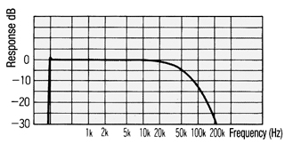
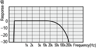
Frequency Characteristics for L-4E5AT (100m)
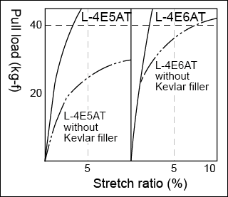
Cable Pull Load and Stretch Ratio
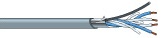
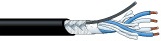
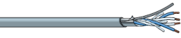
Braided Shield
| Type | Model | Sales units | Nom. O.D. | Weight | Composition | Electrical characteristics | ||||||
|---|---|---|---|---|---|---|---|---|---|---|---|---|
| No. of cond. | Cross sec. area (AWG) and cond. comp. |
Twist pitch | Shield Coverage (braid) | Cond. DCR | Shield DCR | Nom. cap.* | Nom. cap.** | |||||
| m | mm | kg/100m | mm2/(AWG) Q’ty/mm | mm | % | ohm/100m | ohm/100m | pF/m | pF/m | |||
 Jacket colors for L-4E5C: BLKREDORNYELGRNBLUGRYL-4E6S: BLKBRNREDORNYELGRNBLUPPLGRYWHT |
L-4E5C | 100 200 |
4.8 | 3.4 | 4 | 0.15(26) 30/0.08A |
18 | 96% | 13.0 | 2.4 | 162 | 200 |
| L-4E6S | 6.0 | 4.8 | 4 | 0.20(24) 40/0.08A |
20 | 94% | 9.8 | 3.1 | 150 | 185 | ||
 Jacket colors for L-4E5C: GRYBLKL-4E5C: GRY |
L-4E5 | 100 200 |
4.8 | 3.5 | 4 | 0.15(26) 30/0.08A |
18 | 96% | 13.0 | 1.9 | 162 | 200 |
| L-4E6 | 100 200 400 |
6.5 | 6.1 | 4 | 0.23(24) 20/0.12A |
25 | 96% | 8.6 | 1.6 | 144 | 187 | |
Insulation: Cross-linked PE, Jacket: PVC, Dielectric strength: 500V AC/min.
*Capacitance between conductors. **Capacitance between conductor and shield.
Key Features and Benefits / L-4E5C, L-4E6S
- Bend resistant design: the conductor consists of ultrafine 0.08 mm strands offers excellent durability.
- High-density braided shield
Key Features and Benefits / L-4E5, L-4E6
- High-density braided shield
- Drain wire included
Frequency Characteristics for L-4E6S (100m)
The Star Quad Story
Canare Star Quad obtains its name from the 4-conductor style constructionthat minimizes the “loop area” between twists of the conductors. This “double balanced” pairing, reduces susceptibility to electromagnetically induced noise. The improvement in noise rejection is so noticeable, that even SCR dimmer noise (stage lighting consoles), is reduced to less than 1/10 the level found in other 2-conductor microphone cables. Canare Star Quad is designed for use with microphones but is also excellent for all line-level signals (e.g. mixer to power amps). The 4-conductor Star Quad arrangement, cancels electromagnetically induced noise from SCR dimmer packs, fluorescent lighting ballasts and AC power transformers. Handling noise is prevented by use of cotton filler material. Excellent frequency response is maintained due to special irradiated polyethylene insulation which provides a low capacitance dielectric. Canare Star Quad cable with braided shields is super flexible. We use large numbers of thin wire strands in the copper conductors and overall braided shield. We extrude a special compound PVC outer jacket that remains pliant at extremely low temperatures with no wait between cold shipping and installation.

Conductors
All Canare microphone cables utilize high-conductivity, annealed copper wires, stranded to form flexible conductors and shields
Filler
Canare selects cotton, jute and /or exotic polyester fibers for packing. These fillers prevent stretching and twisting of the inner conductors which can cause noise. Additionally, paper, Mylar and/or cloth tape, bind conductors so cables hold their shape.
Jacket
Canare uses specially formulated PVC compounds that combine to make a tough, strong and durable outer jacket with excellent flexibility. These qualities are retained even at very low temperatures, so Canare cables will not stiffen or crack. Available in 10 attractive colors.
Insulation
Canare cables utilize special polymer compounds that reduce capacitive “R-C” filter roll off within the cable and prevent high voltage breakdown. By irradiating the material, the polymer becomes extensively cross-linked, chemically inert, water resistant, and remains flexible at very low temperatures. Irradiated PE is superior to ordinary polyethylene because it is heat resistant. Canare insulation will not shrink back, flow or char when soldering, so you save initial and rework time, and achieve more reliable connections.
Shield
Canare does not use spiral (serve) shields because they can spread apart with use. Our shields are more difficult to manufacture because we use many thin copper strands in a densely woven braid. The shields are super flexible and offer outstanding noise rejection.
In order to maximize noise rejection, Star Quad must be properly wired to the XLR-3 connector (or terminal block).

Because the shield density on Canare Cable is very high, it is somewhat difficult to push back the braid and pull the inner conductors through. Instead, we strongly recommend unbraiding the shield by “combing” it out with a pointed tool, beginning at the end of the cable.

F A Q
Considerations When Contiguring and Selecting Cables for Microphone Systems
With the growing demand of recent years for both greater physical comfort and savings in energy consumption, systems incorporating digital control
based on the latest advances in electronics are coming into wider use for air conditioning and lighting systems. As all these systems come on line,
we cannot help but be reminded of the fact that the wiring used for these digital control systems generates pulse - based electromagnetic noise of the
kind that affects the very delicate signals used in microphone lines.
Microphone cables are designed to carry a range of signals that span the spectrum from 1/100 of a volt (10 mV) to 1/1,000,000 (1 µV). One small
error in wiring procedure or cable selection and the entire microphone system turns into an antenna collecting the surrounding noise.
The following section uses a question and answer format to cover a list of the essential points for configuring microphone systems.
- Under what sort of conditions should a two - conductormicrophone cable be used?
-
The two - conductor microphone cable is suited to environments where noise is not such a great factor and the audio signals are in the comparatively high - 20 dB to 0 dB level range. In such cases, the two - conductor cable offers the advantages of smaller diameter and lower cost. Of course if microphone level, rather than line level, is the criterion being used, star quad cable should be used instead.
- Under what conditions should star quad microphone cable be used?
-
This type is used for environments with a higher noise factor and where audio signals are in the low - 50 dB or less range. This type of cable performs well under noise conditions that exceed the capacity of the two - conductor shielded cable, effectively shielding out over ninety percent more noise.
However, should this type be routed alongside a power cable of any significant capacity it should probably be encased in metal conduit just to be safe.
- Isn’t star quad cable expensive?
-
The cost for this type of cable has fallen significantly in recent years. Several decades ago, cost was so prohibitive a factor that only large musical auditoriums and broadcasting facilities could afford them. Canare succeeded in developing a low- cost star quad cable using aluminum foil in 1981. In addition to traditional professional facilities, this type gained wide use in such non - traditional areas as wedding halls and school lecture rooms.
- When avoiding use of metal conduit, how far away should microphone cable be from power cables?
-
When foregoing the use of protective metal conduit, use the graph shown in as a general guide for distancing cables. Note that ignoring basic guidelines for positioning cables can easily result in noise induction problems which are very difficult to deal with later. Encasing microphone cables in metal conduits is highly recommended for applications that utilize the delicate signal range.

- What considerations are required when using a rack for strong electric current?
-
The same as for the preceding question when metal conduit is not used.
- Would there be any problem with routing the cables through a flexible metal conduit?
-
The flexible conduit would certainly help to reduce noise but would not be as effective as a rigid metal conduit. Use the graph in Fig. 4 as a guide for distancing cables.

- What are the criteria for choosing between the many different types of microphone cables?
-
As all are designed to provide electromagnetic shielding there is not that much basic difference in shielding performance. However, they do differ in various specific characteristics. Cable type should be selected according to specific requirements.
Braided Shield
The braided copper shield is designed to maintain effective shielding performance, regardless of how many times the cable is unwound, bent, twisted or rewound. It is ideal for use as handheld microphone cables or extension cables. This type is more expensive than other types as it is braided very finely to ensure a highly impenetrable shield. Cable termination requires seasoned expertise.
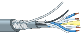
Spiral Shield

The spiral shield consists of several copper wires wound tightly around the cable in a spiral wind. The shielding effect is heightened by winding the shield on twice, each time from different directions in what is referred to as the “double - spiral shield.” The cost range for the spiral shield cable lies roughly mid way between the braided shield and the aluminum foil shield cable. Although cable termination operations are comparatively simple, the spiral shield tends to deteriorate when flexed too frequently. It is designed for stationary installation.
Aluminum Foil Shield
The aluminum foil shield cable consists of aluminum foil fused onto a polyester film and wound around the cable in the form of a tape. Cable termination involves a simple operation and the cable is relatively inexpensive. The aluminum foil cable is recommended for use as stationary cabling. Aluminum foil cable with a Kevlar cable filler is highly recommended for areas where cables will be routed through metal conduit. The Kevlar filler protects the cable as it passes through the conduit, preventing cable breakage or shorting, even when intense stress is applied to the cable. The aluminum foil cable is currently widely used in function halls and multipurpose track and field stadiums.
AWG is for Indicating conductor size
AWG stands for American Wire Gauge. While it is primarily used in North America, it is widely recognized internationally. For solid conductors, the AWG number corresponds to the diameter, whereas for stranded conductors, it is determined by the cross - sectional area. Table provides a list of typical AWG sizes for Canare cables. Complete AWG details can be found on each cable’s product page.
| Type | Solid Conductor | Stranded Conductor | |||||
|---|---|---|---|---|---|---|---|
| Diameter (mm) | Canare Model | Cross Sec Area (mm²) | Canare Model | ||||
| Nominal | Minimum | Nominal | Minimum | ||||
| AWG | |||||||
| 25 | 0.455 | 0.450 | 0.162 | 0.159 | MR202-AT, DA202 | ||
| 24 | 0.511 | 0.506 | 0.205 | 0.201 | L-4E6S, LV-61S | ||
| 23 | 0.574 | 0.569 | L-2.5CHD | 0.259 | 0.254 | L-2T2S | |
| 22 | 0.643 | 0.635 | 0.324 | 0.318 | DMX203, LV-77S, L-3.3CUHWS | ||
| 21 | 0.724 | 0.716 | L-3.3CUHD | 0.412 | 0.404 | ||
| 20 | 0.813 | 0.805 | 0.519 | 0.509 | 4S6, L-4.5CHWS | ||
| 19 | 0.910 | 0.904 | 0.653 | 0.641 | |||
| 18 | 1.020 | 1.016 | L-4.5CHD | 0.823 | 0.807 | GS-6 | |
| 17 | 1.150 | 1.140 | 1.040 | 1.020 | |||
| 16 | 1.290 | 1.278 | L-5.5CUHD | 1.310 | 1.280 | 4S8, 2S7F, L-5.5CUHWS | |
| 15 | 1.450 | 1.435 | 1.650 | 1.620 | |||
| 14 | 1.630 | 1.613 | 2.080 | 2.040 | 4S11, 2S9F | ||
| 13 | 1.830 | 1.800 | L-8CUHD | 2.630 | 2.580 | ||
| 12 | 2.050 | 2.030 | 3.310 | 3.240 | 2S11F | ||