-
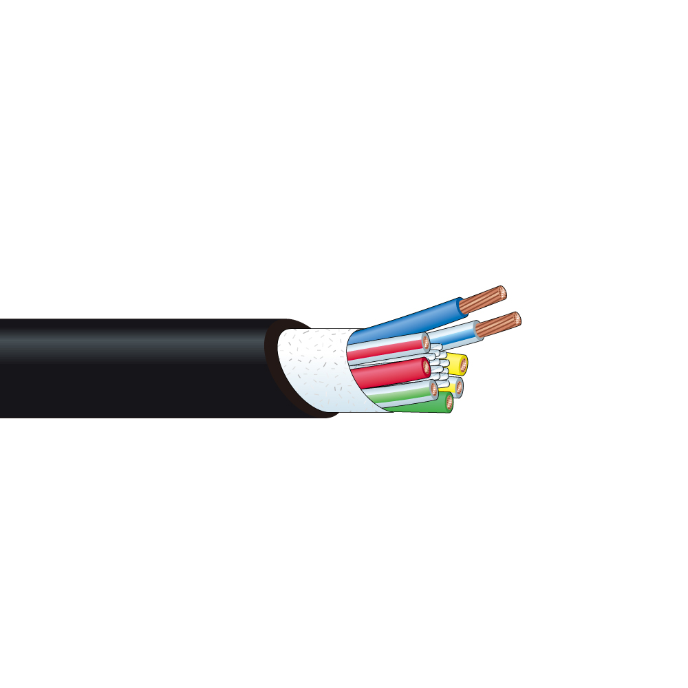
Multicore Speaker Cable
Multicore Speaker Cable
Ideal for multistage use in halls and outdoor events.
- TECH DATA
- TECH NOTE
- DOWNLOAD
Multicore Speaker Cable
| Type | Model | Sales units | Nom. O.D. | Weight | Composition | Electrical characteristics | |||
|---|---|---|---|---|---|---|---|---|---|
| No. of cond. | Cross sec. area and cond. comp. |
Cond. O.D. | Cond. DCR | Nom. capacitance* |
|||||
| m | mm | kg/100m | mm2/(AWG) Q'ty/mm | mm | ohm/100m | pF/m | |||
 Jacket color:
BLK |
8S15G | 100 | 14.9 | 33.0 | 8 | 2.49(14) 98/0.18(OFC) |
3.26 | 0.7 | 51 |
Insulation: polyethylene, Jacket: PVC, Dielectric strength: 500V AC/min.
*Capacitance between adjacent conductors
Key Features and Benefits / 8S15G
- Eight-core speaker cable ideally suited for use with Neutrik speaKON NL8 and a line array speaker.
- Oxygen-free copper (OFC, JIS H3510) conductors.
- Eight-core speaker cable.
- Ideal for use with a line array speaker.
- Oxygen-free copper conductors.
Technical Note
Four-conductor Configuration Minimizes Noise
Speaker cable must accommodate relatively high signal levels, typically tens to hundreds of watts of RMS power. Electromagnetic interference (EMI) can radiate from these speaker lines directly into adjacent low voltage cables (i.e. microphone, video, lines, etc.). Canare solves this problem by using a 4-conductor “Star Quad” configuration in all of our 4S-series speaker cables. Because every conductor is located the same distance from center, the opposing magnetic fields are cancelled out. Attenuation of magnetic field radiation is superior when compared to a standard 2-conductor speaker wire.

Four-conductor cable

Two-conductor cable
Selecting the Right Speaker Cable
Always try to keep speaker cables as short as possible and select cable models that offer a higher damping factor; 20-50 for music (i.e. connect sound) and 10-20 for speech (i.e. sport stadiums).
The greater the damping factor (DF), the better the ability to control speaker excursion to create sharp, clear quality in the low end frequency range

As the above formula shows, a higher conductor resistance causes a lower damping factor, which prevents even top quality power amps from performing at peak optimum levels.
Speaker Cable Length obtained from the Damping Factor (reference)
| Model | Cross-sec. Area | Cond. Resist. | Cond. Resist. for Total Loop |
Cable Length (m) | |
|---|---|---|---|---|---|
| mm2 /AWG | ohm/100m | ohm/m | DF = 20 | DF = 50 | |
| 4S6(G) | 1.02/17 (pair) | 1.85 | 0.037 | 9.5 | 3.0 |
| 4S8(G) | 2.52/14 (pair) | 0.75 | 0.015 | 23.3 | 7.3 |
| 4S11(G) | 4.36/11 (pair) | 0.45 | 0.009 | 38.9 | 12.2 |
| 4S10F(G) | 3.50/15 (pair) | 0.55 | 0.011 | 31.8 | 10.0 |
| 4S12F(G) | 5.62/13 (pair) | 0.35 | 0.007 | 50.0 | 15.7 |
| 4S14F(G) | 8.00/12 (pair) | 0.25 | 0.005 | 70.0 | 22.0 |
| 4S18F(G) | 14.16/9 (pair) | 0.15 | 0.003 | 116.7 | 36.7 |
| S410-*P | 2.00/18 (pair) | 0.95 | 0.019 | 18.4 | 5.8 |
| 2S7F(G) | 1.27/16 | 1.5 | 0.030 | 11.7 | 3.7 |
| 2S9F(G) | 2.18/14 | 0.9 | 0.018 | 19.4 | 6.1 |
| 2S11F(G) | 3.62/12 | 0.5 | 0.010 | 35.0 | 11.0 |
| 2S14F(G) | 5.63/10 | 0.3 | 0.006 | 58.3 | 18.3 |
| 2S15G | 2.49/14 | 0.7 | 0.014 | 25.0 | 7.9 |
Conditions: Speaker impedance = 8 ohm, Power amplifier output impedance = 0.05 ohm