-
BCA-TL -
BCA-TS
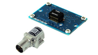
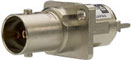
3G-SDI Active BNC
Small BNC connector incorporates either a cable equalizer or a cable driver.
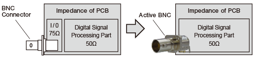
Active BNC makes innovation in your 3G-SDI PC board layout.
- TECH DATA
- TECH NOTE
3G-SDI Active BNC
| Type | Model | Form | Type | Built-in | Sales unit |
|---|---|---|---|---|---|
 |
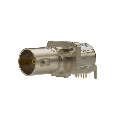
BCA-TL | Right Angle | TX | Cable Driver | 5 |
| BCA-RL | RX | Cable Equalizer | |||
 |
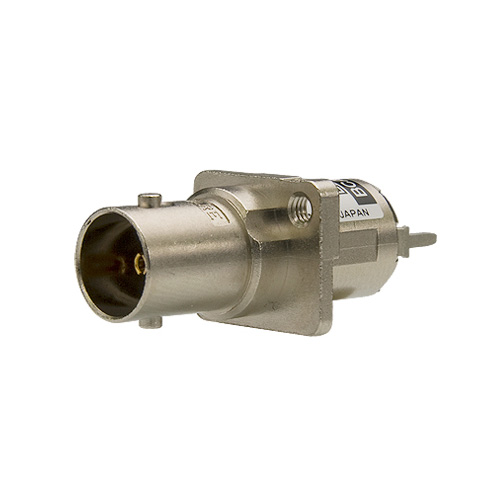
BCA-TS | Straight | TX | Cable Driver | |
| BCA-RS | RX | Cable Equalizer |
Key Features and Benefits
- BNC connector integrated with a cable equalizer or a cable driver, and yet keep the connector size to a minimum.
- Support 3G/HD/SD-SDI
- Offers an excellent return loss performance without designing 75 ohm I/O Circuit
- Simplifies PCB design process dramatically and will reduce entire development cost
- PCB space saving and help to downsize devices
- TX/RX identification by insulation color
Simplify Your Circuit Design
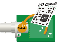
Simplify Your Circuit Design
Specifications
| TX BCA-TL, BCA-TS | RX BCA-RL, BCA-RS | |
|---|---|---|
| Supply Voltage | DC 3.3 V | |
| Current Consumption | 50 mA | 70 mA |
| Operating Temperature | - 25 deg C to +85 deg C | |
| Output Amplitude | 800 mVpp | N/A |
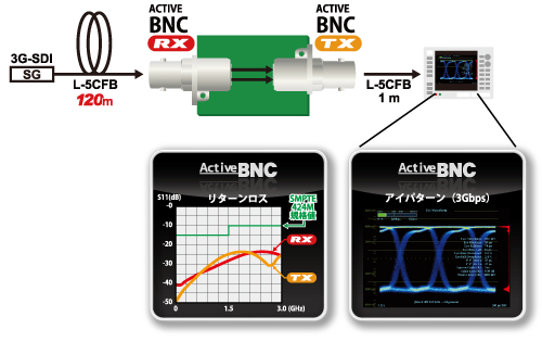
| Equalization | N/A | 3G-SDI 120m over L-5CFB |
| Standards | SMPTE ST 424, 292, 259, BTA S-004C, EN 50083-9 | SMPTE ST 424, 292, 259, BTA S-004C, EN 50083-9 |
| Weight | 9 g | |
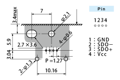
Panel Hole Dim.
| BCA-TL | BCA-RL | BCA-TS | BCA-RS | |
|---|---|---|---|---|
| Panel Hole Dim. |  t1.6 Screw: M2.6 |
 t1.6 Screw: M2.6 |
||
| PCB Hole Dim. | 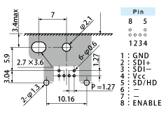 t2.0 (TOP VIEW) |
 t2.0 (TOP VIEW) |
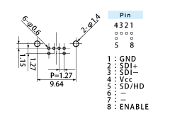 t2.0 (TOP VIEW) |
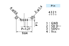 t2.0 (TOP VIEW) |
The dark shaded areas come into contact with the connector body.
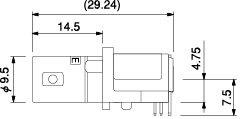
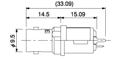
Dimensions
Technical Note
Voltage Standing - wave Ratio (VSWR) and Return Loss
Terminating the receiving end of a limited length coaxial cable using a resistance value not equal to its characteristic impedance creates a reflected wave that returns back down the cable to the sending end. The result is interference developing between the travelling wave and the return wave which results in a standing wave that causes voltage levels to fluctuate. The degree to which terminating resistance matches the characteristic impedance is indicated using the VSWR or voltage standing-wave ratio standard shown in Fig. 1. Going hand in hand with the VSWR ratio is the return loss factor which measures the size of the reflected wave current in relation to the travelling wave current. (See Fig. 2)
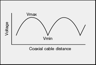
Fig. 1 Voltage Distribution Over Coaxial Cable
| VSWR | Return Loss (dB) |
|---|---|
| 2 | 9.54 |
| 1.5 | 13.98 |
| 1.2 | 20.83 |
| 1.1 | 26.44 |
| 1.05 | 32.26 |
| 1.02 | 40.09 |
| 1.01 | 46.06 |
Fig. 2 VSWR to Return Loss Conversion Table