-

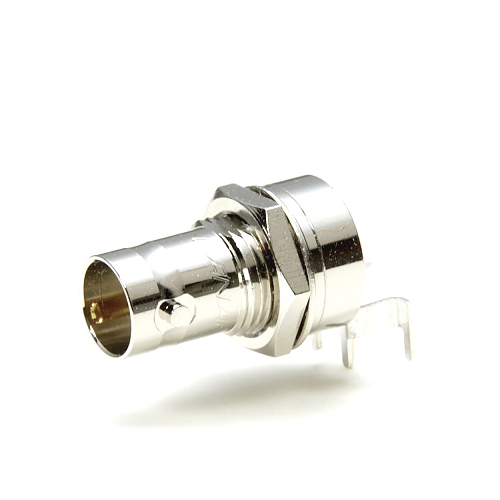
BCJ-FPLV-12G -
BCJ-FPLVA -
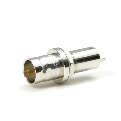
BCJ-FPLV01 -
BCJ-FPLV-L -
BCJ-FPLHA -
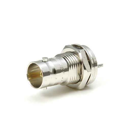
BCJ-FPC -
BCJ-FPC02 -
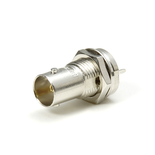
BCJ-RPC -
BCJ-RPC/1 -

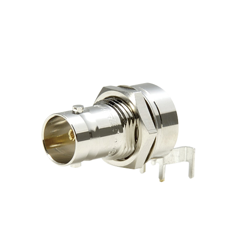
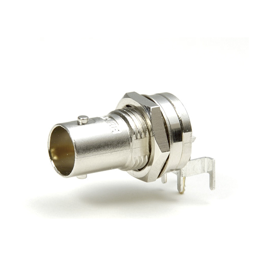
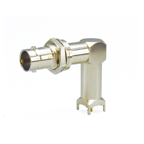
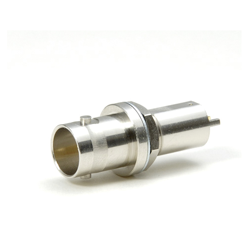
75 ohm BNC PCB Mount Receptacles (Hex Nut Type)
BCJ-FP and RP Series are 75 ohm BNC connectors which have a hex nut and lock washer for front or rear-mounting on a panel.
- TECH DATA
- TECH NOTE
- DOWNLOAD
75 ohm BNC PCB Mount Receptacles (Hex Nut Type)
| Type | Model | Description | Stud Position | Panel Mount | Standard package |
|---|---|---|---|---|---|
 |
BCJ-FPLV-12G | Right Angle, for 12G-SDI | Vertical | Front: Hex nut and lock washer |
20pcs / 100pcs |
 |
BCJ-FPLVA | Right Angle | |||
 |
BCJ-FPLV01 | Right Angle, Low Cost | |||
 |
BCJ-FPLV-L | Right Angle, Long Neck | 10pcs | ||
 |
BCJ-FPLHA | Right Angle | Horizontal | 20pcs / 100pcs | |
 |
BCJ-FPC | Straight | - | ||
 |
BCJ-FPC02 | Straight, Low Cost | - |
| Type | Model | Description | Stud Position | Panel Mount | Standard package |
|---|---|---|---|---|---|
 |
BCJ-RPC | Straight, Through Hole Mount | - | Rear: Hex nut and lock washer |
20pcs / 100pcs |
 |
BCJ-RPC/1 | Straight, Surface Mount | - |
Key Features and Benefits
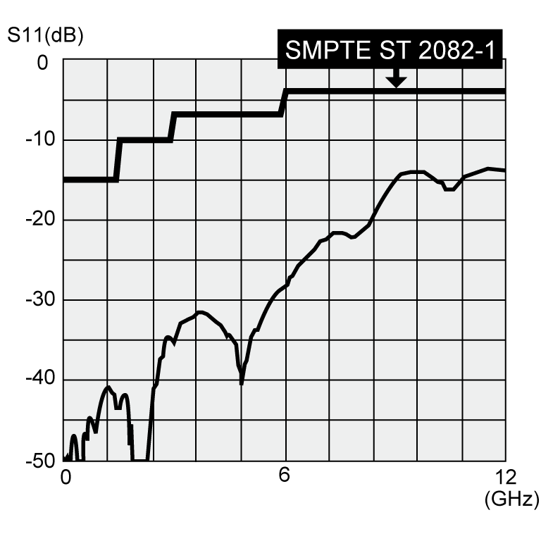
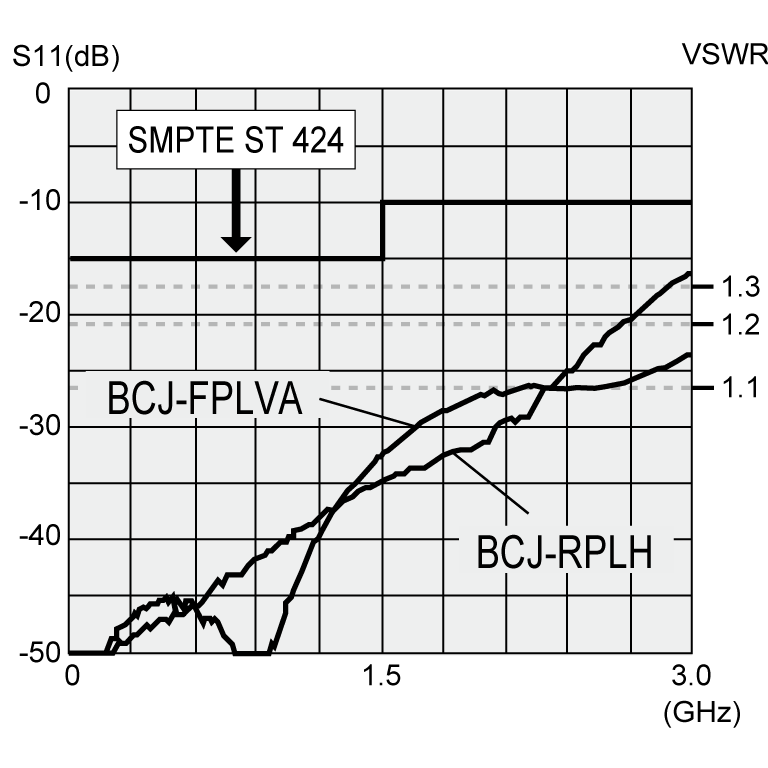
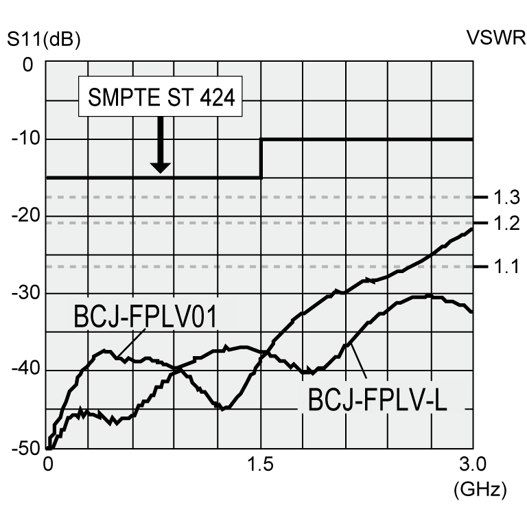
- BCJ-FPLV-12G is specially designed to minimize the return loss for 12G-SDI
- Return loss:
BCJ-FPLV-12G: 15 dB @ 6 GHz, 10 dB @ 12 GHz,
BCJ-FPLV-L: 26.4 dB @ 3 GHz, Others: 26.4 dB @ 1 GHz.
- Note:
- Any cleaning solvents cannot be used. This leads to insulation problems.
Insulation material: m-PPO (m-PPE)
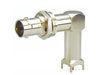
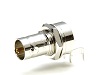
BCJ-FPLV-12G
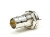
BCJ-FPLVA
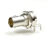
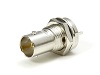
BCJ-FPLV01, BCJ-FPLV-L
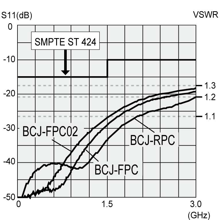
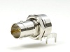
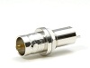
BCJ-FPC, BCJ-FPC02, BCJ-RPC
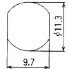
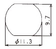
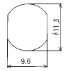
Panel Hole Dimensions
| BCJ-FPLV-12G*, BCJ-FPLVA* BCJ-FPLV01*, BCJ-FPLV-L* |
BCJ-FPLHA* | BCJ-FPC* BCJ-FPC02* |
BCJ-RPC/1, BCJ-RPC |
|---|---|---|---|
 |
 |
 |
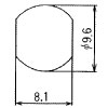 |
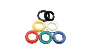
* BCP-FP series accept insulation bushing IU-7/16, and the panel hole for IU-7/16 should be adopted in this case.
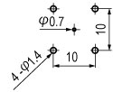
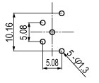
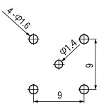
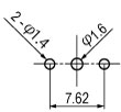
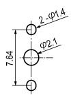
PC Board Hole Dimensions
| BCJ-FPLV-12G | BCJ-FPLVA BCJ-FPLV01 BCJ-FPLHA |
BCJ-FPLV-L | BCJ-FPC BCJ-FPC02 |
BCJ-RPC |
|---|---|---|---|---|
t2.0 |
t2.0 |
t2.0 |
t2.0 |
t2.0 |
Technical Note
Voltage Standing - wave Ratio (VSWR) and Return Loss
Terminating the receiving end of a limited length coaxial cable using a resistance value not equal to its characteristic impedance creates a reflected wave that returns back down the cable to the sending end. The result is interference developing between the travelling wave and the return wave which results in a standing wave that causes voltage levels to fluctuate. The degree to which terminating resistance matches the characteristic impedance is indicated using the VSWR or voltage standing-wave ratio standard shown in Fig. 1. Going hand in hand with the VSWR ratio is the return loss factor which measures the size of the reflected wave current in relation to the travelling wave current. (See Fig. 2)
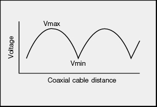
Fig. 1 Voltage Distribution Over Coaxial Cable
| VSWR | Return Loss (dB) |
|---|---|
| 2 | 9.54 |
| 1.5 | 13.98 |
| 1.2 | 20.83 |
| 1.1 | 26.44 |
| 1.05 | 32.26 |
| 1.02 | 40.09 |
| 1.01 | 46.06 |
Fig. 2 VSWR to Return Loss Conversion Table