-
Bantam patch panel 481U-820AQ -
Bantam patch panel 48-12A/820AQ/EIA -
Bantam wired box 481U-WB* -
Bantam wired box 48WB-* -

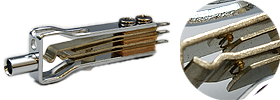
Cross bar contact
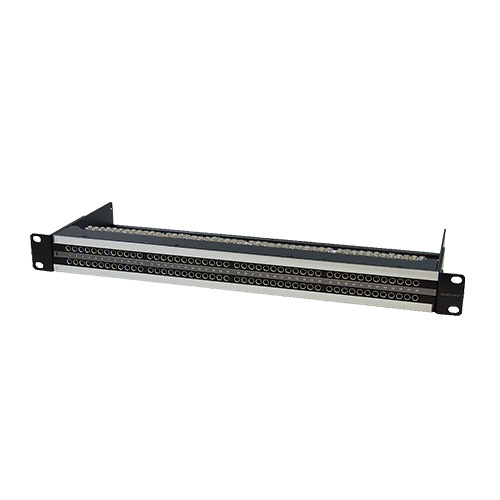
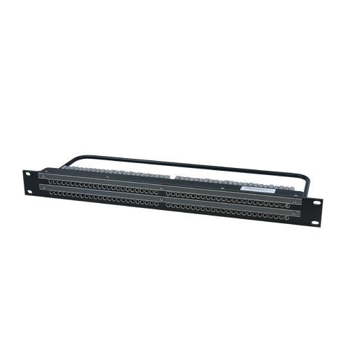
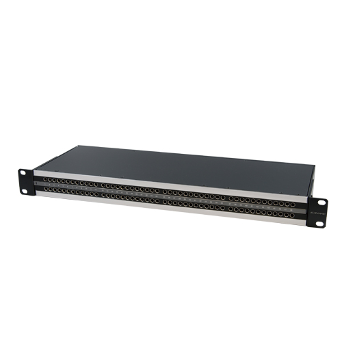
Bantam Patchbays
Our audio patchbay with capacity for 48 jacks per row.
- TECH DATA
- TECH NOTE
- DOWNLOAD
Bantam Patchbays
| Type | Model | Description | Connector | Standard package |
|---|---|---|---|---|
| Bantam | 481U-820AQ | 1U | 820AQ×96 | 1 |
| Bantam | 48-12A/820A/EIA | 1U | 820AQ×96 | 1 |
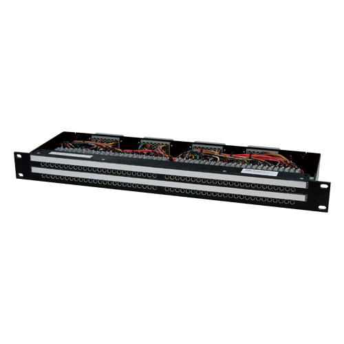
Wired Box (Bantam Patchbays)
| Type | Model | Panel Size | Connector | Standard package | |
|---|---|---|---|---|---|
| Front | Rear | ||||
|
Bantam
|
481U-WBF | 1 RU | 820AQ × 96 | 90-602 × 4 | 1 |
| 481U-WBH | 1 RU | 820AQ × 96 | 90-602 × 4 | 1 | |
| 481U-WBW | 1 RU | 820AQ × 96 | 90-602 × 4 | 1 | |
| 481U-WBS | 1 RU | 820AQ × 96 | 90-602 × 4 | 1 | |
| 48WB-F | 1 RU | 820AQ × 96 | 90-602 × 4 | 1 | |
| 48WB-H | 1 RU | 820AQ × 96 | 90-602 × 4 | 1 | |
| 48WB-W | 1 RU | 820AQ × 96 | 90-602 × 4 | 1 | |
Key Features and Benefits
- Broadcasting Stations, Recording Studios.
- Number of Holes and Rows.
1RU, 96 holes, 2 rows. - 481U patchbay can be recessed 25 mm by changing the screw positions on the mounting brackets.
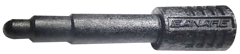
- The gold alloy cross bar contact, which features a low faulty contact rate, is used for the jacks.
- Note:
- *481U-WB* can be recessed 25 mm
- Note:
- *90-602 connector is identical to ELCO 00-8016-090-∗∗∗-702V connector
Wired Panels (Bantam Patchbays)
| Type | Model | Panel 1 | Panel 2 | Standard package | ||
|---|---|---|---|---|---|---|
| Size | Connector | Size | Connector | |||
|
Bantam
|
48XP-F | 1 RU | 820AQ × 96 | 3 RU x 2 | XLR3-31F77 x 48 XLR3-32F77 x 48 |
1 |
| 48XP-H | 1 RU | 820AQ × 96 | 3 RU x 2 | XLR3-31F77 x 48 XLR3-32F77 x 48 |
1 | |
| 48XP-W | 1 RU | 820AQ × 96 | 3 RU x 2 | XLR3-31F77 x 48 XLR3-32F77 x 48 |
1 | |
- Note:
- *Cables are 2 meters in length.
Audio Patchbays (Bantam) Related Products
| Model | Description | Standard package |
|---|---|---|
| 820AQ | Bantam Jack | 1 |
| ABJ-DC | Bantam Jack Dust Cap | 100 pcs |
| PH50B | Bantam Patch Cord Holder | 1 set |
| DS10-AS1 | Designation Strip for Bantam | 2 pcs |
| ABP-DPNEW | Bantam Dummy Plug | 10 pcs |
| ABP-TANEW | 600 Ohm Bantam Terminating Plug | 1 pc |
ABP-DP

ABP-TA
820AQ
Technical Note
Audio Patchbay Normalling Descriptions
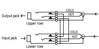
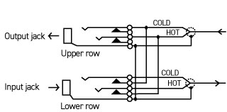
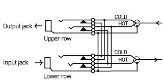
Output from a device is obtained from the upper row, while input to a device is normally connected to the lower row. Users can select from the following three types of connecting functions.
| F: Full normal connection | H: Half normal connection | W: Double normal connection |
|---|---|---|
 |
 |
 |
|
Full Normal Format (series) The upper (output) row is connected to the lower row (input) in the state when a plug is not inserted. When a plug is inserted in the upper jack to obtain a signal, the signal is not connected to the lower jack. A signal can be entered by inserting a plug in the lower jack. In this case the signal is not connected to the upper jack. |
Half Normal Format (half-parallel) The upper (output) row is connected to the lower row (input) in the state when a plug is not inserted. When a plug is inserted in the upper jack to obtain a signal, the signal is connected to the lower jack. This format allows the signal to be obtained in parallel. The signal can be prevented from going to the lower jack by inserting a dummy plug. Signals are input by inserting a plug in the lower jack. In this case the signal is not connected to the upper jack. |
Double Normal Format (series-parallel) The upper (output) row is connected to the lower row (input) in the state when a plug is not inserted. When a plug is inserted in the upper jack to obtain a signal, the signal is connected to the lower jack. This format allows the signal to be obtained in parallel. The signal can be prevented from going to the lower jack by inserting a dummy plug. A signal can be entered by inserting another plug in the lower jack. Note that the signal in this case is connected to the upper jack. This can be prevented by inserting a dummy plug. |
90 - 602 Connector Format (Wired box)
| 4 | 3 | 2 | 1 | |
|---|---|---|---|---|
| Bantam | Lower row 25~48 ch | Upper row 25~48 ch | Lower row 1~24 ch | Upper row 1~24 ch |
| Skini | Lower row 17~32 ch | Upper row 17~32 ch | Lower row 1~16 ch | Upper row 1~16 ch |
90-602 connector is mated with 90-608 connector.
90-608 requires either 125 or 525 contact and 90-T cover for assembling.

* The numbers in parentheses are ELCO ordering codes.
** Crimping pliers for 525 : 06-1001-015 (AWG #18), 06-1001-016 (AWG #20-#22), 06-1001-017 (AWG #24-#26).
| 32WB-* | 481U-WB*, 48-WB-* | HOT | COLD | SHIELD | ||||
|---|---|---|---|---|---|---|---|---|
| Cdhannel no. | 1 | 17 | 1 | 25 | A | H | R | |
| 2 | 18 | 2 | 26 | B | J | S | ||
| 3 | 19 | 3 | 27 | C | K | T | ||
| 4 | 20 | 4 | 28 | D | L | U | ||
| 5 | 21 | 5 | 29 | E | M | V | ||
| 6 | 22 | 6 | 30 | F | N | W | ||
| 7 | 23 | 7 | 31 | X | AE | AM | ||
| 8 | 24 | 8 | 32 | Y | AF | AN | ||
| 9 | 25 | 9 | 33 | Z | AH | AP | ||
| 10 | 26 | 10 | 34 | AA | AJ | AR | ||
| 11 | 27 | 11 | 35 | AB | AK | AS | ||
| 12 | 28 | 12 | 36 | AC | AL | AT | ||
| 13 | 29 | 13 | 37 | BJ | BD | BY | ||
| 14 | 30 | 14 | 38 | BK | BT | BZ | ||
| 15 | 31 | 15 | 39 | BL | BU | CA | ||
| 16 | 32 | 16 | 40 | BM | BV | CB | ||
| 14 | 30 | 17 | 41 | BN | BW | CC | ||
| 15 | 31 | 18 | 42 | BP | BX | CD | ||
| 16 | 32 | 19 | 43 | CF | CN | CW | ||
| 14 | 30 | 20 | 44 | CH | CP | CX | ||
| 15 | 31 | 21 | 45 | CJ | CR | Cy | ||
| 16 | 32 | 22 | 46 | CK | CS | CZ | ||
| 14 | 30 | 23 | 47 | CL | CT | DA | ||
| 15 | 31 | 24 | 48 | CM | CU | DB | ||