-
FP-C4 -
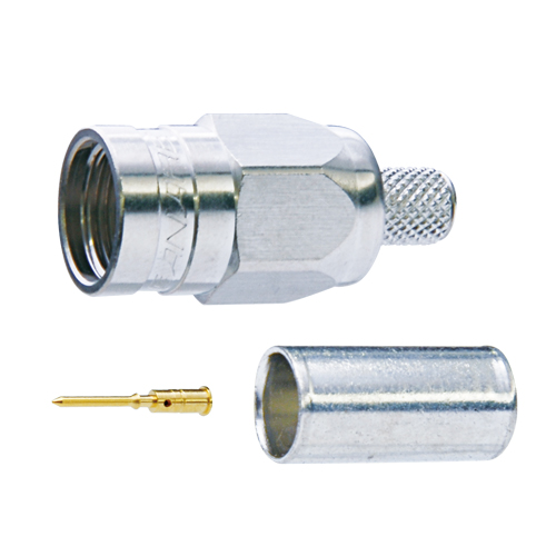
FJ-FPC
F Connectors
This type is used in such applications as home television receivers for cable television (CATV) systems.
- TECH DATE
- TECH NOTE
- DOWNLOAD
F Connectors
| Model | Suitable Cable | Center Pin | Sleeve | Boot | Die Set | Standard package |
|
|---|---|---|---|---|---|---|---|
| Canare | Others | ||||||
| FP-C25HD | L-2.5CHD | - | BN1003B | BN7129 | - | TCD-35CA | 20 pcs / 100 pcs |
| FP-C3 | L-3C2VS, L-3C2VS, V*-3C | - | BN1002B | BN7003A | CB24 | TCD-35CA | |
| FP-C31 | L-3C2W | - | BN1002B | BN7011 | CB25 | TCD-31C | |
| FP-C3F | L-3CFB, V*-3CFB | - | BN1003B | BN7003A | CB24 | TCD-35CA | |
| FP-C4 | LV-61S | 8241, 8279, RG-59B/U | BN1003B | BN7015A | CB25 | TCD-4CA TCD-451CA |
|
| FP-C4F | L-4CFB, V*-4CFB | 1505A, 1505ANH, 8212, 8241F, 9167, 9259, 9659 | BN1004B | BN7015A | CB25 | TCD-4CA TCD-451CA |
|
| FP-C5 | L-5C2VS, L-5C2V, V*-5C | - | BN1004B | BN7016 | CB26 | TCD-35CA | |
| FP-C52 | L-5C2W | - | BN1004B | BN7014 | - | TCD-451CA | |
| FP-C53A | L-4.5CHD | 1694A, 9066, 9116, 9118, 9248 | BN1005B | BN7046 | CB26 | TCD-35CA | |
| FP-C55A | - | 1695A, 89120, 87120, 633948, 9116P | BN1005B | BN7045A | - | TCD-35CA | |
| FP-C5F | L-5CFB, V*-5CFB | - | BN1005B | B75004A | CB26 | TCD-5CF TCD-55FA |
|
| FP-C71A | - | 7731A, 9064, 9292, 1617A, 9011 | BN1041A | BN7021A | - | TCD-7CA | |
| FP-C7FA | L-7CFB | - | BN1030A | BN7021A | - | TCD-7CA | |
Key Features and Benefits
- Lock mechanism improves reliability by preventing shifting or detaching of the center pin.
- The tools and cable stripper can be used for the Canare crimp BNC plugs as well, thus saving on extra equipment.
- VSWR of 1.1 or less up to 2 GHz.
- Designed for indoor use.
- Note:
- Be sure to use Canare Crimp Tool.
| Model | Description | Standard package |
|---|---|---|
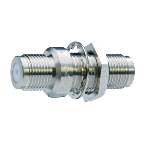
| FJ-JR | Jack to Jack | 20 pcs / 100pcs |
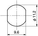
| FJ-FPC | PC Board Straight Mount |
Key Features and Benefits
- VSWR of 1.1 or less up to 2 GHz.
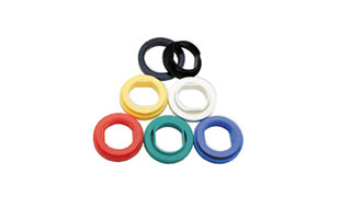
- Accept insulation bushing IU-7/16.
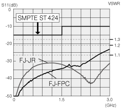
Return loss for FJ-FPC and FJ-JR
| Panel Mount Hole Dimensions | PC Hole Dimensions | |
|---|---|---|
FJ-JR |

FJ-FPC |
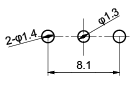
FJ-FPC |
| Model | Description | Flange Type | Standard package |
|---|---|---|---|
| FJ-JRU | Jack to Jack | ITT XLR-F77 | 20 pcs |
| FJ-JRUD | Jack to Jack | Neutrik D | |
| FJ-JRUDB | Jack to Jack | Neutrik D (Black) |
Key Features and Benefits
- Three types of flanges are available.
Technical Note
Voltage Standing - wave Ratio (VSWR) and Return Loss
Terminating the receiving end of a limited length coaxial cable using a resistance value not equal to its characteristic impedance creates a reflected wave that returns back down the cable to the sending end. The result is interference developing between the travelling wave and the return wave which results in a standing wave that causes voltage levels to fluctuate. The degree to which terminating resistance matches the characteristic impedance is indicated using the VSWR or voltage standing-wave ratio standard shown in Fig. 1. Going hand in hand with the VSWR ratio is the return loss factor which measures the size of the reflected wave current in relation to the travelling wave current. (See Fig. 2)
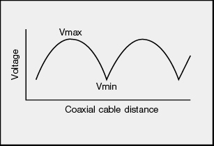
Fig. 1 Voltage Distribution Over Coaxial Cable
| VSWR | Return Loss (dB) |
|---|---|
| 2 | 9.54 |
| 1.5 | 13.98 |
| 1.2 | 20.83 |
| 1.1 | 26.44 |
| 1.05 | 32.26 |
| 1.02 | 40.09 |
| 1.01 | 46.06 |
Fig. 2 VSWR to Return Loss Conversion Table